IB Physics: Circuit Question with Two Cells
- Tyler Buffone

- Feb 11
- 4 min read
Updated: Feb 12
In IB Physics, circuit problems can sometimes involve multiple cells placed at different points in a circuit. These questions test your understanding of Kirchhoff’s laws, potential differences, and current flow. In this post, we’ll break down a circuit with two cells, step by step, to help you master this concept. Whether you're preparing for an exam or just looking to strengthen your understanding, this explanation will guide you through the key principles needed to solve these types of problems with confidence.
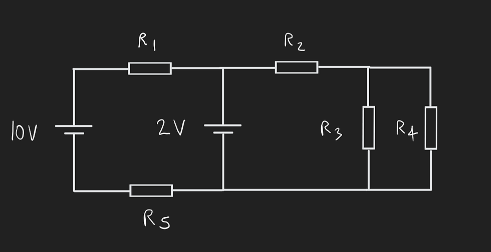
Given the following circuit and the resistance of each resistor, determine the potential differences and currents for each resistor.
Resistance of resistor 1 = 5 Ω.
Resistance of resistor 2 = 2 Ω.
Resistance of resistor 3 = 10 Ω.
Resistance of resistor 4 = 5 Ω.
Resistance of resistor 5 = 5 Ω.
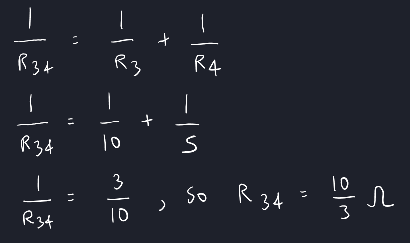
The first thing to do is simplify the circuit.
Resistors 3 and 4 are in parallel, which means we can calculate their total resistance.
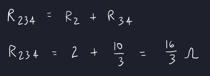
This combined resistor is in series with resistor 2, so we can calculate their total resistance.
We can now draw a simplified circuit as follows. We have also included the direction of the current. Note that "I" with a subscript of "T" represents the total current and "I" with a subscript of "S" represents the split current.
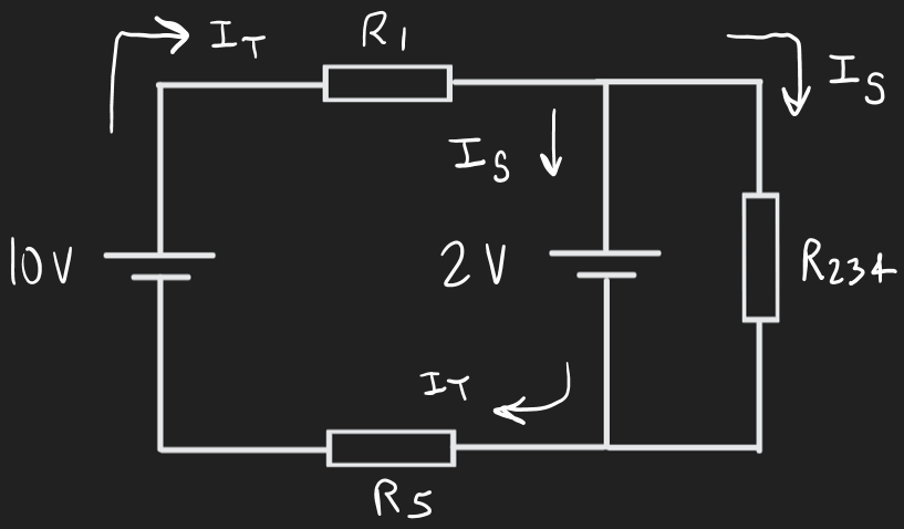
The current will flow from the 10 V cell and pass through the first resistor. It will then split up at the first junction. By Kirchhoff's First Law (the Current Law, Junction Law, or Nodal Law), the current will split up at the first junction and then recombine at the bottom junction in the above diagram before continuing through resistor 5 and ending at the negative end of the 10 V cell.
Note that Kirchhoff's First Law therefore tells us that the current through resistor 5 will be the same as the current through resistor 1.
Moreover, by Kirchhoff's Second Law (the Voltage law or Loop Rule), the voltage drop around a loop must equal zero before the current finishes at the negative end of the 10 V cell.
This law applies whether you're considering the small loop that doesn't include the combined resistor on the right side of the diagram or the large loop that includes the combined resistor but does not include the second 2 V cell.
For this example, we will consider the former of the two options.
This allows us to find the current and voltage through the first resistor as follows:
Preliminary remark: for the first line, remember that V = RI and we know the resistors but not the currents.
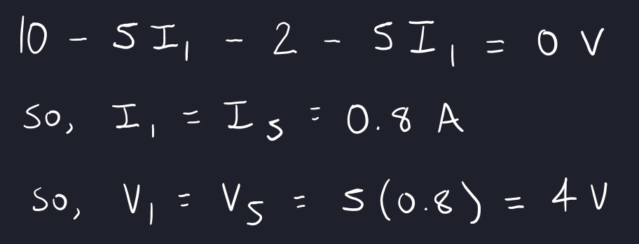
Notice that the voltage will drop from 10 V to 6 V due to the first resistor, which means that the first junction's voltage is 6 V. This is larger than the 2 V cell that follows it, so the current will just flow through this 2 V cell. As it passes through the cell, the voltage will then drop again by 2 V. This is why we subtracted 2 in the above calculation.
Since the first resistor causes a voltage drop of 4 V and the fifth resistor causes a voltage drop of 4 V, it must be that the combined resistor causes a voltage drop of 2 V (this must be true because of Kirchhoff's Second Law). This allows us to calculate the current that would pass through the combined resistor.

But be careful, this is the combined current throughout the combined resistor that combines resistors 2, 3, and 4. Based on the original diagram provided, this combined current must pass through resistor 2 before separating at the junction that immediately follows it; the two resulting split currents will then re-combine to a value of 0.375 A when they reach the junction at the bottom right of the first given diagram (by Kirchhoff's First Law). Therefore, we can calculate the voltage drop at the second resistor.

Since the combined resistor must cause a voltage drop of 2 V, and resistor 2 causes a voltage drop of 0.75 V, it must be that resistors 3 and 4 each have a voltage drop of [2 - 0.75] = 1.25 V by Kirchhoff's Second Law. Note that an application of Kirchhoff's Second Law is that resistors in parallel experience the same voltage drop.
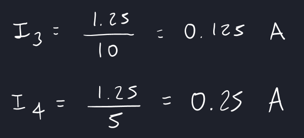
Finally, we can calculate the current going through resistors 3 and 4, which completes the question.
We will now list all of the unrounded values for the potential differences and currents for each of the five resistors. Resistor 1 (5 Ω):
V = 4 V
I = 0.8 A
Resistor 2 (2 Ω):
V = 0.75 V
I = 0.375 A
Resistor 3 (10 Ω):
V = 1.25 V
I = 0.125 A
Resistor 4 (5 Ω):
V = 1.25 V
I = 0.250 A
Resistor 5 (5 Ω):
V = 4 V
I = 0.8 A
Finally, we will list the final answers rounded to one significant figure.
Resistor 1 (5 Ω):
V = 4 V
I = 0.8 A
Resistor 2 (2 Ω):
V = 0.8 V
I = 0.4 A
Resistor 3 (10 Ω):
V = 1 V
I = 0.1 A
Resistor 4 (5 Ω):
V = 1 V
I = 0.3 A
Resistor 5 (5 Ω):
V = 4 V
I = 0.8 A